Description
GE IS200EDEXG1BBB — EX2100e Exciter De-Excitation Control Board
Product Overview
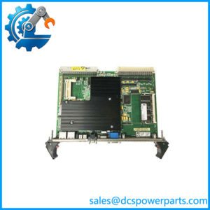
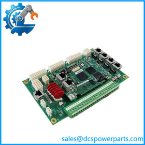
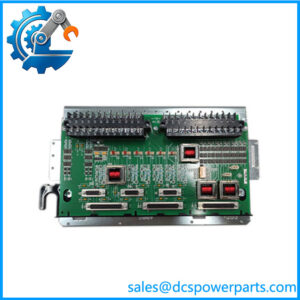
The GE IS200EDEXG1BBB is an EDEX de-excitation control board used in GE EX2100/EX2100e excitation systems. Its principal function is to manage the firing signals used by the SCR-based de-excitation circuitry when generator field energy must be discharged. During a shutdown or field-circuit interruption, the excitation system must remove stored magnetic energy from the generator field in a controlled manner. The EDEX board participates in this process by coordinating firing commands with the associated excitation transfer circuitry and monitoring conduction feedback.
The EDEX assembly is not simply a general-purpose digital output card. Its firing circuits are part of a specific generator-excitation function, where signal timing, circuit configuration, and feedback status matter to the overall protection sequence. GE documentation describes the EDEX function as including de-excitation SCR firing, conduction-sense feedback, and voltage retention to support operation during a control-power failure. The exact hardware configuration must match the installed system, particularly where multiple EDEX boards are used as master and follower units. A board with a similar appearance or related model number should not be assumed interchangeable without an approved cross-reference.
For plant maintenance and procurement teams, GE IS200EDEXG1BBB is a critical spare to evaluate against the installed board’s complete part number and revision markings. Before replacement, verify the Group 1 SCR de-excitation configuration, associated EXTB and control-board connections, field-circuit arrangement, and any jumper or wiring settings specified by the original drawings. Confirm that the replacement has been functionally tested, rather than relying solely on a power-on inspection. After installation, the complete de-excitation sequence should be checked using the manufacturer’s approved procedure. This is especially important because an incorrect board configuration can affect the response of the generator-field discharge circuit during a trip or shutdown.
Product Introduction (Non-Templated)
When a generator trip opens the field circuit, stored magnetic energy still has to be discharged. The GE IS200EDEXG1BBB supports this critical step in the EX2100/EX2100e excitation system by coordinating SCR firing and monitoring conduction feedback.
For replacement work, match the full board number and revision, confirm the SCR de-excitation configuration, and verify the associated EXTB wiring. A visual match is not sufficient for a generator-protection circuit.
Key Technical Specifications
| Parameter | Specification |
|---|---|
| Manufacturer | General Electric (GE) |
| Model | IS200EDEXG1BBB |
| Functional Acronym | EDEX |
| Product Type | Exciter de-excitation control board |
| System Family | EX2100 / EX2100e excitation control |
| Primary Function | De-excitation SCR firing and conduction-sense feedback |
| De-Excitation Group | Group 1 — SCR-based configuration |
| Nominal Control Voltage | 24 VDC, reported by secondary component listings; verify against system drawings |
| Input Filter | Hardware filter, 4 ms, as reported in supplier specifications |
| Functional Revision | B, according to component references |
| Secondary Revision | BB, according to component references |
| Instruction Manual | GEI-100466 |
| Associated Control Hardware | EXTB and related excitation-system control circuitry |
| Board Configuration | May depend on master/follower arrangement and approved system wiring |
| Operating Temperature | −30°C to +65°C, reported in supplier listings; verify against the applicable manual |
| Mounting / Installation | Installed in the compatible excitation-system assembly; confirm exact cabinet and connector arrangement |
| Communication Protocol | No general-purpose communication protocol established for this board |
| Condition | Verify actual stock condition and functional-test status |
Specification note: The nominal voltage, filter timing, and temperature range above are reported in secondary component listings. Confirm them against the GE documentation applicable to the installed equipment before using them as acceptance criteria.
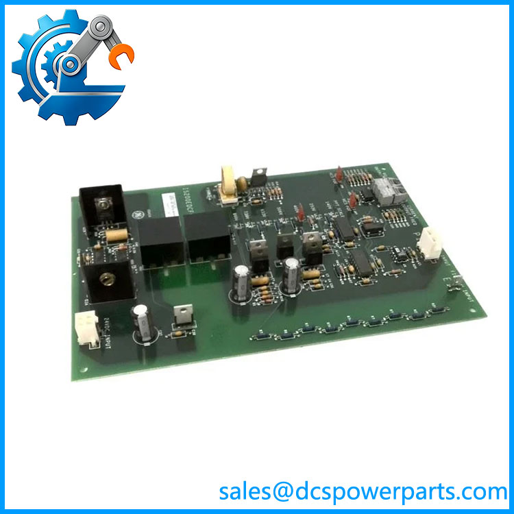
IS200EDEXG1BBB
Related Products
The following boards and accessories are associated with the EX2100/EX2100e de-excitation architecture. They perform different functions and should not be treated as direct replacements for the IS200EDEXG1BBB.
- EXTB — Exciter Transfer Board: Coordinates field-circuit switching and associated de-excitation signals. Verify the exact EXTB model and circuit configuration when troubleshooting the overall shutdown sequence.
- EMIO — Exciter Module I/O Board: Provides relevant excitation-system input/output functions and can initiate the de-excitation sequence. Confirm the installed version and control architecture.
- IS200EAUXH1AAA — EAUX Auxiliary I/O Board: Supports auxiliary excitation-system I/O functions. It is a separate board with a different role from the EDEX de-excitation circuit.
- EDEX Follower Board: In systems using multiple EDEX boards, follower units may receive firing-control signals from the master arrangement. Confirm the exact follower part number and wiring before replacement.
- EPL2 Interconnection Cable: A 25-pin D-connector cable is described in component references for interconnecting follower EDEX boards. Verify cable pinout and system applicability before use.
- GEI-100466 — EDEX Instruction Manual: A relevant documentation reference for the EDEX board family. Confirm the manual revision and its applicability to the installed hardware.
- GE EX2100e Excitation Control System: The wider excitation platform in which the board operates. The full system configuration determines the correct replacement and commissioning procedure.
- Generator Field Breaker or Contactor Circuit: The switching arrangement interacts with de-excitation logic and feedback. Confirm auxiliary-contact wiring and the discharge-circuit design against the plant drawings.
Frequently Asked Questions
Q1. What is the GE used for?
It controls the SCR firing function associated with generator-field de-excitation in GE EX2100/EX2100e excitation systems. It also supports conduction-sense feedback and voltage retention functions described in EDEX documentation.
Q2. Does use SCR or diode de-excitation?
The is identified with the Group 1 SCR de-excitation configuration. GE EDEX variants may differ by de-excitation circuit type, so verify the exact part number and installed discharge-circuit design before selecting a replacement.
Q3. What does the 24 VDC specification mean?
Supplier listings report a nominal 24 VDC excitation/control voltage for this board. Do not interpret that value as the generator-field voltage or as a complete statement of every board supply requirement. Verify the terminal-level requirements from the applicable system drawings.
Q4. Can I replace the board while the generator is running?
Do not assume live replacement is permitted. The EDEX board participates in a generator-protection function, and the associated field circuit can contain stored electrical energy. Follow GE’s approved isolation procedure and the site’s lockout/tagout requirements. Any post-replacement test should be performed by qualified personnel under an approved commissioning plan.
Q5. Does the support a master/follower configuration?
The EDEX architecture can use a master board with follower boards in applicable installations. The exact arrangement depends on the system design and wiring. Confirm board roles, interconnection cables, and firing-signal routing from the installed drawings rather than assuming every EDEX assembly uses the same configuration.
Q6. How do I verify compatibility with my existing EX2100e system?
Compare the full part number, functional and secondary revision markings, de-excitation group, connector arrangement, and jumper settings. Check the equipment BOM and GEI-100466 or the applicable system manual. Obtain engineering approval before substituting a different revision or board variant.
Q7. What should I request when buying surplus or refurbished stock?
Request clear photographs of the identification labels and PCB, confirmation of the board’s condition, and documented functional-test results. Ask whether the unit has been repaired or modified and whether warranty coverage applies. For a protection-critical assembly, an inspection report alone is not a substitute for an appropriate functional test.
Q8. How should the system be tested after replacement?
Use the manufacturer’s approved procedure to verify the board configuration, firing-control signal path, conduction feedback, and relevant field-circuit interlocks. Confirm that the de-excitation sequence behaves as designed under an authorized test plan. Do not initiate an uncontrolled live trip solely to test the replacement board.