Description
Cummins HMI211
Product Introduction
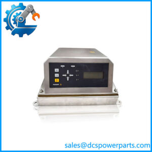
The Cummins HMI211 is a PowerCommand human-machine interface designed for operator interaction with Cummins generator-set control systems. Its role is more specific than that of a general-purpose industrial HMI: it provides the display, status indication, menu navigation, and operator controls required to monitor and operate a compatible generator set. Cummins documentation identifies the HMI 211 Remote Unit for use with PCC1302 and describes communication through the PCCNet network. In this configuration, the remote panel can be installed up to 4,000 feet (1,219 m) from the generator set when the installation provides adequate power for the distance.
The Cummins HMI211 provides access to generator electrical and engine information through its menu system, including AC voltage, current, power, power factor, frequency, and engine-related data. The front panel uses a graphical LED-backlit LCD and tactile controls rather than a touchscreen. Cummins documentation for PowerCommand 1.1 identifies a 128 × 64 pixel display, four multifunction membrane switches, fixed-action controls, and status indicators for conditions such as Remote Start, Not in Auto, Shutdown, Warning, Auto, and Run/Manual Run.
From a replacement standpoint, the Cummins HMI211 should be treated as a system-specific operator interface rather than an independent PLC or generic display terminal. The control architecture, generator-set model, PowerCommand controller, firmware/configuration, and exact HMI part number should be checked before substitution. Cummins lists 0541-1394 as an HMI 211 Remote Unit, while other HMI211-related part numbers appear in service and replacement documentation. That distinction matters when replacing an installed panel because similar HMI211 hardware can exist in different generator-control configurations.
Technical Specifications
| Parameter | Specification |
|---|---|
| Product Model | Cummins / HMI 211 |
| Manufacturer | Cummins |
| Product Type | Generator Set HMI / Operator Panel |
| Product Family | PowerCommand |
| Primary Application | Cummins generator-set monitoring and control |
| Display Type | Graphical LED-backlit LCD |
| Display Resolution | 128 × 64 pixels |
| Communication | PCCNet in documented remote-unit applications |
| Operator Controls | Multifunction soft keys plus fixed-action/navigation controls |
| Status Indication | Remote Start, Not in Auto, Shutdown, Warning, Auto, Run/Manual Run |
| Information Display | AC voltage, current, power, PF, frequency, engine information and fault information |
| Configuration / Diagnostics | Supported through the PowerCommand operator interface |
| Dimensions | Approx. 112 × 142 × 35 mm |
| Mounting | Panel / remote operator-panel installation |
| Documented Remote Distance | Up to 4,000 ft / 1,219 m with appropriate power provisions |
| Cummins Remote Unit Part Number | 0541-1394 |
| System Compatibility | Must be matched to the applicable PowerCommand controller and generator-set configuration |
Cummins gives the HMI 211 Remote Unit dimensions as approximately 112 mm × 142 mm × 35 mm and identifies 0541-1394 as its ordering number.
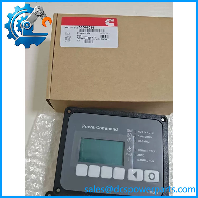
Cummins HMI211
Main Features and Engineering Considerations
1. Dedicated PowerCommand Operator Interface
is intended to work within Cummins generator control architecture. It is not a general-purpose PLC HMI that can simply be connected to an arbitrary controller. The communication path, firmware, displayed parameter set, and available control functions depend on the associated PowerCommand control system.
2. Generator Metering and Status Information
The interface provides practical operating information rather than functioning merely as an alarm annunciator. Cummins documentation identifies access to AC voltage, current, power, power factor, frequency, and engine information. Fault history and active fault information can also be reviewed from the operator interface.
3. Direct Operator Control
The incorporates dedicated controls for operating modes and navigation. Documentation describes Off, Auto, and Manual Run functions together with menu navigation and configurable soft-key functions. This makes the unit part of the operational control chain, not just a passive display.
4. Replacement Risk
For procurement, the phrase “” alone is not always sufficient identification. Check the complete label, Cummins part number, generator model, PowerCommand controller type, and software/firmware information. A visually identical panel can still be unsuitable if its programmed configuration does not correspond to the installed control system.
5. Remote Installation
Cummins documentation specifically describes remote installation through PCCNet, with distances up to 4,000 feet under appropriate power-supply conditions. Installations approaching the maximum distance require attention to conductor resistance, voltage drop, communication wiring, grounding, and the actual system architecture rather than relying only on the nominal communication distance.
6. Field Replacement Check
Before replacing an , record the existing display’s part number and configuration information. Photograph the connector and wiring arrangement, confirm the associated PowerCommand controller, and preserve any configuration or calibration information required by the generator-set application. Do not assume that a replacement panel with the same front-panel designation is automatically plug-and-play.
Application Scenarios
- Cummins PowerCommand generator sets
- Standby and emergency generator systems
- Prime-power generator installations
- Industrial generator control panels
- Facility power systems
- Data-center generator systems
- Commercial building standby power
- Remote generator operator stations
- Generator monitoring and fault-acknowledgment panels
Engineer’s Guide: Field Pitfalls
Do not treat as a standalone PLC. Its value comes from its integration with the Cummins PowerCommand control architecture.
Do not order solely from the HMI designation. Verify the complete Cummins part number. Cummins documentation identifies 0541-1394 as an HMI 211 Remote Unit, while other -related configurations and part numbers exist.
Check the controller before changing the panel. PCC1302 and PowerCommand 1.1 documentation both reference , but the exact system configuration determines what the display can show and control.
Do not overlook communication wiring. A panel can power up while still failing to communicate correctly with the generator controller. Check the communication network, termination, cable condition, grounding, and distance-related voltage drop.
Record the existing configuration before removal. For an operating generator, capture active faults, configuration information, controller identification, and HMI identification before disconnecting the original unit.
Frequently Asked Questions
Is Cummins a PLC?
No. is a generator-set operator interface associated with Cummins PowerCommand control systems. The main generator control functions reside in the associated PowerCommand controller.
What does display?
Depending on the connected PowerCommand system, it can provide generator electrical measurements, engine information, operating status, alarms, fault history, configuration information, and diagnostic information.
Does have a touchscreen?
The documented uses a graphical LCD with tactile membrane/soft-key controls rather than a modern touchscreen interface.
What is the Cummins part number for ?
Cummins identifies 0541-1394 as the HMI 211 Remote Unit in its Power Generation accessories documentation. Other -related part numbers may appear in generator-specific service documentation, so the installed unit’s complete part number should be checked before procurement.
Can any replace another ?
Not automatically. Compatibility should be confirmed against the generator-set model, PowerCommand controller, firmware/configuration, connector arrangement, and complete Cummins part number.
Procurement Note
For a replacement , the safest purchasing specification is the complete part number from the installed nameplate, not simply “.” For an operational generator, request confirmation of the associated PowerCommand controller and configuration before installation. If the replacement is refurbished or previously installed, functional testing of the LCD, membrane keys, LED indicators, communication interface, and controller handshake should be part of incoming inspection.