Description
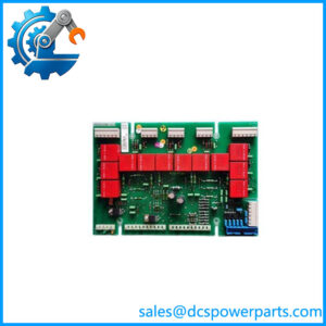
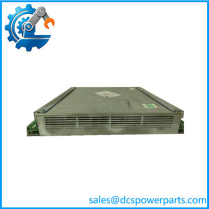
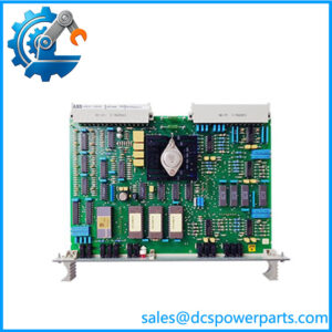
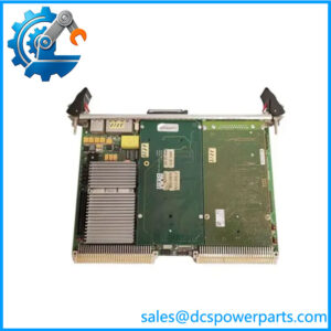
ABB ROM810
Product Introduction
A turbine controller often has enough logic capacity to command an output but not the contact rating required by the final field device. ABB ROM810 addresses that interface problem by providing two electromechanical relays with Form C contacts for higher-load switching. ABB designed the module to connect directly to the TP800, VP800 and AS800 turbine specialty modules.
The ROM810 is particularly relevant where turbine control outputs must operate inductive loads such as solenoids. ABB specifies 5 A at 120 VAC and 3 A at 150 VDC, with built-in inductive kickback suppression and relay-coil activation feedback. The module also provides power-failure feedback and connectors intended for 2oo3 applications.
Key Technical Specifications
| Parameter | Specification |
|---|---|
| Manufacturer | ABB |
| Product Model | ROM810 |
| Product Type | Relay Output Module |
| System | Symphony Plus Turbine Automation |
| Compatible Modules | TP800, VP800, AS800 |
| Relay Type | Electromechanical |
| Number of Relays | 2 |
| Contacts per Relay | 2 Form C |
| Contact Arrangement | Changeover |
| AC Contact Rating | 5 A @ 120 VAC |
| DC Contact Rating | 3 A @ 150 VDC |
| Inductive Load Protection | Built-in inductive kickback suppression |
| Relay Feedback | Coil activation feedback |
| Power Monitoring | Power-failure feedback |
| Redundancy Interface | Connectors for 2oo3 applications |
| Connection | Direct plug-in connection to compatible turbine module |
| Typical Application | Solenoids and other heavy-duty turbine-control outputs |
ABB’s turbine documentation directly specifies the two-relay, Form C architecture and the 5 A / 3 A contact ratings.
Major Features / Advantages
Two Independent Electromechanical Relays
The ROM810 contains two electromechanical relays, providing a practical interface between a turbine specialty controller and field devices requiring a higher-current switching contact. Each relay provides two Form C contacts, giving the engineer normally-open and normally-closed switching paths rather than a simple transistor-style output.
This arrangement is useful in turbine applications where the output state itself matters during a fault or trip condition. The normally closed side can be incorporated into an appropriate permissive, alarm, or interlock design where the overall system architecture calls for it.
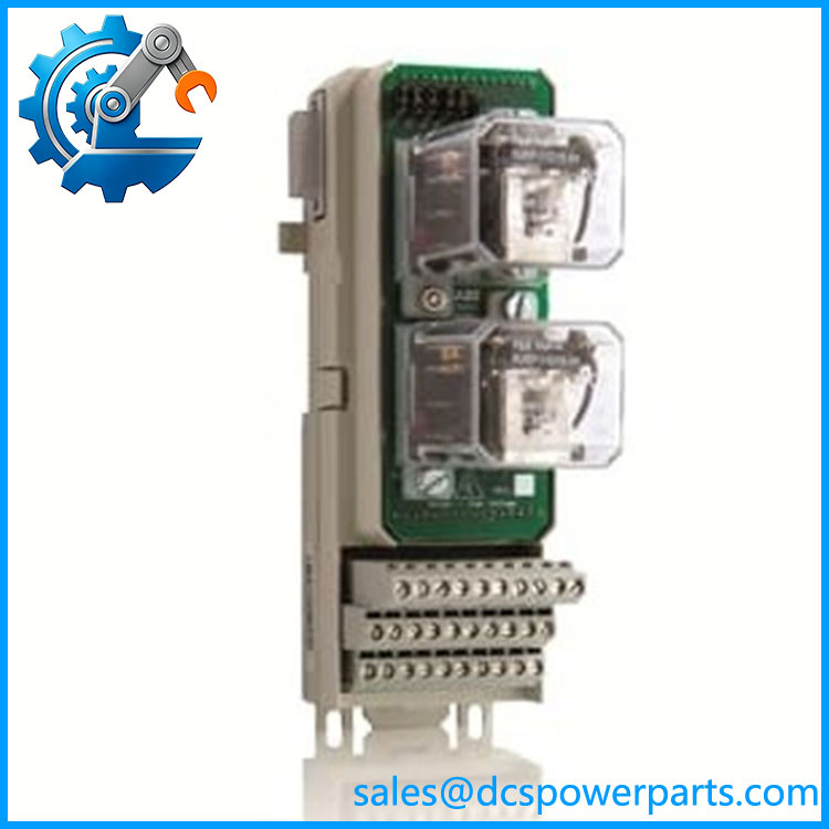
ROM810
Heavy-Duty Output Switching
ABB specifically describes the ROM810 as providing heavy-duty relay output capability for loads such as solenoids. The published ratings are 5 A at 120 VAC and 3 A at 150 VDC. These values describe contact capability; they should not be interpreted as permission to switch any arbitrary load continuously at those ratings. Load type, inrush, switching frequency, suppression, and required electrical certification still need to be considered.
Inductive Kickback Suppression
Solenoid and relay coils generate inductive voltage when de-energized. ABB incorporates inductive kickback suppression into the , which is particularly relevant in turbine cabinets containing repeated solenoid switching.
This does not eliminate the need to check the field device and circuit design. External suppression may still be required depending on the load, wiring arrangement, and control-circuit requirements.
Relay Activation Feedback
The module provides relay-coil activation feedback. That gives the turbine-control architecture a means of monitoring whether the relay has been activated rather than relying entirely on the command signal sent by the controller.
For commissioning and fault diagnosis, this distinction is useful: a controller output command, relay activation, and final field-device response are three different points in the signal chain.
Power-Failure Feedback
ABB also specifies power-failure feedback on the . In turbine protection and control applications, this can provide important diagnostic information when a relay output does not behave as expected.
2oo3 Application Support
The includes connectors for 2oo3 applications, which is relevant to turbine protection architectures where voting arrangements are used to reduce the consequences of a single-channel fault. The presence of the connector does not by itself make a complete turbine trip system 2oo3 or establish a particular safety integrity level; that depends on the complete engineered architecture.
Compatibility With Modern Symphony Plus Turbine Modules
ABB’s newer Symphony Plus documentation continues to identify as a relay-output accessory for SD-series turbine modules. The documentation describes its use for heavy-duty relay outputs that can in many cases be wired directly to final elements such as trip solenoids, test solenoids, and generator breakers.
Application Scenarios & Pain Points
Turbine Trip Solenoids
The is suited to applications where the turbine control system must interface with solenoid-operated final elements. Its relay contacts provide the electrical switching interface required between the controller and field circuit.
Generator Breaker Interfaces
ABB documentation identifies generator-breaker applications among the final-element use cases for in Symphony Plus turbine systems.
Test Solenoid Control
Where turbine maintenance procedures require controlled actuation of test solenoids, the relay output arrangement provides a physical contact interface rather than a low-current semiconductor output.
Redundant Turbine Protection
The 2oo3-related connections make the module relevant to architectures where multiple channels participate in a voted trip arrangement. The actual voting logic and safety architecture must be verified from the turbine system drawings rather than inferred from the alone.
Related Products
- ABB TP800 — turbine protection module designed to work with for relay output capability.
- ABB VP800 — turbine valve-positioning/control module compatible with .
- ABB AS800 — turbine auto-synchronization module compatible with .
- ABB SIM810 — serial interface module used for configuration and firmware-related servicing of the turbine specialty modules.
- ABB TBU810 — termination unit associated with the 800-series turbine modules.
- ABB EIM810 — Extended I/O Module providing additional predefined hardwired I/O for turbine specialty modules.
- ABB CPM810 — common processing module used within the 800-series turbine specialty architecture.
- ABB TP01 — newer Symphony Plus SD-series turbine protection module; ABB documentation lists as an external relay-output option.
These are related system components, not blanket replacement recommendations.
Engineer’s Guide: Field Pitfalls to Avoid
1. Do not confuse with a conventional digital-output module.
is an electromechanical relay interface. Its switching behavior, contact ratings, coil characteristics, and mechanical life need to be considered differently from a solid-state DO module.
2. Check the actual load, not just the nominal current.
The published 5 A AC and 3 A DC values are contact ratings. Solenoid inrush, inductive energy, switching frequency, and suppression can materially affect contact stress.
3. Verify the controller family.
was designed to connect directly with the TP800, VP800 and AS800 turbine modules. Do not assume that any ABB 800-series I/O module can mechanically or electrically substitute for it.
4. Treat 2oo3 wiring as a system-level issue.
The has connectors for 2oo3 applications, but the complete voting architecture must be checked. A relay accessory by itself does not establish a particular safety architecture.
5. Check the normally open and normally closed paths carefully.
Each relay has Form C contacts. During commissioning, verify which contact is used for the energized and de-energized state rather than relying on a generic “relay output” description.
6. Do not overlook inductive suppression.
The module includes kickback suppression, but the field load and circuit design still need to be reviewed. This is particularly important for solenoid-operated turbine trip equipment.
7. Inspect the physical relay module before installation.
For a legacy spare, check relay condition, connector integrity, board markings, terminal condition, and evidence of contact arcing or overheating. Verify the actual inventory condition rather than relying solely on a catalog description.
FAQ
What is ABB ?
ABB is a Relay Output Module for ABB’s Symphony Plus turbine automation architecture. It provides two electromechanical relays for heavy-duty output switching.
How many relays does have?
contains two electromechanical relays. Each relay provides two Form C contacts.
What are the relay contact ratings?
ABB specifies 5 A at 120 VAC and 3 A at 150 VDC. These are contact ratings, so the actual permissible load should be checked against the specific load type and switching duty.
Which ABB modules are compatible with ?
The original ABB documentation identifies TP800, VP800 and AS800 as compatible turbine specialty modules. Newer Symphony Plus SD-series documentation also identifies as a relay-output accessory for SD turbine modules.
Can directly drive a solenoid?
It was specifically designed to provide heavy-duty relay output capability suitable for inductive loads such as solenoids. The actual solenoid voltage, current, inrush, suppression and trip-circuit design must still be checked before installation.
Does provide relay diagnostics?
The documented module provides relay-coil activation feedback and power-failure feedback. These signals can help distinguish a controller command problem from a relay or power problem during troubleshooting.
Is a safety-rated turbine protection module by itself?
No. is a relay-output accessory. Its use in a 2oo3 or turbine-trip architecture must be evaluated as part of the complete control and protection system. The module’s 2oo3 connectors do not by themselves establish the safety integrity of the complete installation.