Description
Key Technical Specifications
| Parameter | Specification |
|---|---|
| Product Model | AL129A |
| Associated Order Code | CD101152 |
| Product Type | Chopper converter power supply |
| Input Voltage | 96–253 VAC |
| Input Frequency | 50/60 Hz |
| Output 1 | 5 VDC, up to 10 A |
| Output 2 | 12 VDC, up to 4 A |
| Typical Rated Power | 120 W |
| Output Isolation | Isolated DC outputs |
| Switching Frequency | Approximately 60 kHz, according to secondary technical records |
| Communication Protocol | Not applicable as a power-conversion module |
| Operating Temperature | Approximately -20°C to +60°C |
| Installation | Plug-in rack module |
| Compatible Racks | AM163 / AM164 / AM166 |
| Backplane | FB178 |
| Architecture | Single or redundant power configuration |
The 96–253 VAC input range and 5 VDC/12 VDC outputs are consistently reported across available technical records. The 10 A and 4 A output limits should be treated as module ratings, not as an indication that every installed rack configuration can continuously consume the combined maximum.
Product Introduction
The GE AL129A is a rack-mounted power-conversion module associated with the Alstom ALSPA CE2000/CE3000 control platform. Its primary job is electrical rather than computational: it converts the incoming AC supply into isolated low-voltage DC rails used by processor, I/O, communications, and other rack electronics. The module is documented for AM163, AM164, and AM166 rack assemblies through the FB178 backplane.
The important procurement distinction is that AL129A is not a CPU or general-purpose automation controller. Some supplier databases incorrectly describe it as a CPU motherboard. Technical repair documentation instead identifies AL129A as a Martek power-supply board used in Alspa P320/CE2000 equipment.
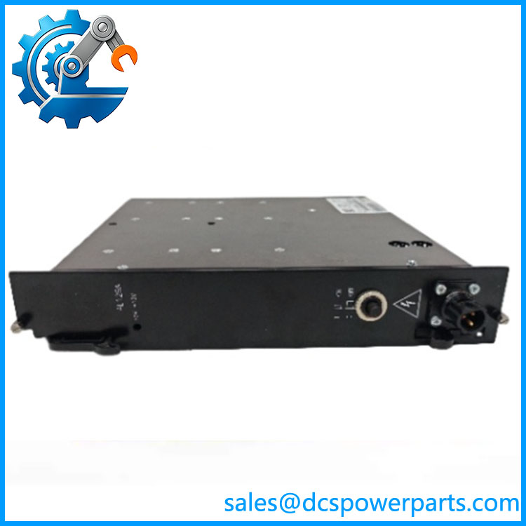
GE AL129A
Engineering Pain Point
When an AL129A begins failing, the symptom can appear at the system level rather than at the power module itself: processors may fail to boot, multiple rack cards may disappear simultaneously, or intermittent resets can occur. Replacing individual I/O cards before checking the rack power rails can therefore waste considerable troubleshooting time. The first diagnostic step should be to confirm the AC input and measure the 5 VDC and 12 VDC rails under the actual rack load.
Typical Applications
- ALSPA CE2000/CE3000 control racks — supplies the rack’s low-voltage electronic assemblies.
- Power-generation control systems — including legacy turbine and plant-control installations.
- HVDC and grid-control installations — where legacy ALSPA control hardware remains in service.
- Legacy DCS maintenance — particularly where maintaining the existing rack is preferable to a complete control-system migration.
Technical Pitfalls to Avoid
- Do not order solely by “GE AL129A.” The Alstom/Martek/GE naming history is inconsistent across databases. Confirm the board label, CD101152 code, revision, and rack application.
- Do not confuse the power module with the CPU. provides rack power; it does not execute the control application.
- Check both DC rails during diagnosis. A module can produce one rail while the other is degraded, producing confusing downstream faults.
- Verify rack compatibility before substitution. AM163, AM164, and AM166 compatibility is documented, but that does not make every visually similar ALSPA power board interchangeable.
- Check redundant-power wiring. If two supplies are installed, verify the intended redundancy/load-sharing arrangement rather than assuming any two boards can be paralleled.
- Inspect the rack backplane and connectors. A replacement module cannot correct a burned connector, oxidized contact, or damaged backplane power path.
Related Products
- AL129B — reported as a related/updated power-module variant; verify electrical and mechanical compatibility before substitution.
- AL119 — another Martek power-supply board in the same broader repair family, but not automatically interchangeable with .
- AL120 — related Martek power-supply hardware; application and output configuration require verification.
- AL122 — another Martek supply-board reference documented for Alspa equipment.
- AM163 — compatible CE2000 rack platform documented for .
- AM164 — another rack assembly associated with .
- AM166 — expansion/rack platform documented with .
- FB178 — backplane interface associated with the installation.
- UT150 — Alspa CE2000 controller hardware commonly associated with this rack ecosystem; exact power requirements should be checked against the installed configuration.
Procurement Note
For a replacement, specify + complete board/order code such as CD101152, then verify the rack type, board revision, connector arrangement, output ratings, and existing single/redundant power architecture. Do not accept a supplier’s generic “GE ” description as sufficient identification. The available evidence shows that this is a legacy Alstom/Martek power-conversion design whose manufacturer lineage is often represented inconsistently in modern inventories.